Requirements for Boiler and Pressure Vessel Manufacture Licensing
|
3.Resource Pressure Vessel Manufacturer |
||||
|
5. Safety quality reqirements |
Chapter 5
Quality Requirements for Boiler and Pressure Vessel Products
Section 1 Safety quality requirements of boilers
Article 44
General requirements
The boilers produced by boiler manufacturer should meet the requirements of the following safety technical codes and regulations.
1. Technical Supervision Regulation for Safety of Steam Boilers
2. Technical Safety Supervision Regulation for Hot Water Boilers
3. Technical Safety Supervision Regulation for Organic Fluid Heaters
4. Technical Safety Supervision Regulation for Small and Atmospheric Hot Water Boilers
Manufacturers outside China, who have difficulties to completely carry out the above-mentioned regulations, are allowed to adopt the technical codes and standards, which is conventional and complete in system and are used by most countries after having approved by Boiler and Pressure Vessel Safety Supervision Administration of AQSIQ. But, in this case, they must meet the requirement as stipulated from article 45 to 50 onwards simultaneously.
Article 45
Requirements of steel for pressure components of boiler
Steel for pressure components of the boiler (including staying components) must be killed-steels. The designations of the steel should be those listed in foreign boiler steel standards, or of conventional boiler steels.
Article 46
Requirements for boiler structure
The structure of boiler should be in complete accordance with above-mentioned Chinese safety technical regulations for boilers.
Article 47
Requirements product inspection
The results of visual inspection of boiler, mechanical property testing of welded joint, metallograpy and fractography, hydrostatic pressure test, and the NDE items and detective rate must satisfy the requirements of above-mentioned Chinese boiler codes and regulations.
Article 48
The requirements for safety appurtenances and metering devices
1. The spring-loaded safety valves for steam boilers should be of the full lift type.
2. The spring-loaded safety valve with threaded connection should be connected with a stub and the latter should be welded to the drum or the header.
3. Pressure gauge and thermometer should be of SI unit.
4. Two independent water-level gauges should be mounted on the drum of every steam boiler. Only one gauge may be mounted if one of the following conditions is met:
1) For boilers with a rated capacity not greater than 0.5 t/h.
2) For boilers with a rated capacity not greater than 2 t/h, and equipped with a set of reliable water level controlling device.
3) For boilers provided with two sets of independent remote water level display devices.
4) For electric heating boilers
5. For boilers with a rated capacity not less than 2 t/h, the low/high water level alarms and low water level interlock-protection device should be provided. For boilers with rated capacity not less than 6 t/h, the over-pressure alarm and the over-pressure interlock device should be provided.
6 For coal-fired, oil-fired, or gas-fired boilers, the ignition sequence controller and extinguish protection devices should be provided.
7. For hot water boilers with rated temperature of outlet water not less than 120 °C or with rated heating capacity not less than 4.2 MW, the over-temperature alarm should be provided.
Article 49
Requirements for delivery documents
The following safety-related technical documents are required when the boilers are to be delivered.
1. Boiler drawing (including general drawing, installation drawing and drawings of main pressure parts).
2. Strength Calculation sheets for pressure components and the calculation sheets for relieving capacity of safety valves (or selected from operational manual of the safety valves) or a summary of above mentioned calculation results.
3. Product quality testifying documents (including product certificate of compliance, material mill sheets for main pressure parts, NDE reports, post-welding heat treatment reports and hydrostatic pressure test report).
4. Installation and operational manual for the boiler.
5. Boiler with rated pressure equal to or greater than 3.8MPa should also attach to the following documents:
1). Calculation sheets for thermodynamic, wall temperature of super-heater, and for fuel gas resistance or a summary of the above calculation results.
2). System thermal expansion diagram.
6. For boilers with rated pressure not less than 9.8 MPa, the following additional documents should be provided:
1). The calculation sheets for the wall temperature of re-heater and for boiler water circulation or a summery of the calculation results.
2). Diagram of the steam-water system of the boiler.
Article 50
Requirements for nameplate
A metallic nameplate should be put on the conspicuous place on the boiler. The contents on the nameplate should include at least the following items (in Chinese or English and using SI units):
1. Name and address of manufacturer,
2. Level and serial number of manufacture license,
3. Rated steam capacity (thermal power),
4. Rated steam pressure (outlet pressure),
5. Rated steam temperature (outlet temperature),
6. Steam temperature at inlet and outlet of the re-heater (not applicable for the boilers without re-heaters),
7. Manufacturing number of the boiler,
8. Manufacturing date.
Section 2 Basic requirements for the safety quality of pressure vessels
Article51
General requirements
Pressure vessels produced by pressure vessel manufacturers should meet the requirements of the following Chinese pressure vessels' safety technical codes and regulations:
1. Safety Technical Supervision Regulations for Pressure Vessel,
2. Safety Supervision Regulations for Super-high Pressure Vessels,
3. Safety Supervision Regulation on Baric Oxygen Chamber for Medical Treatment,
4. Safety Supervision Regulations for Gas Cylinders,
5. Safety Supervision Regulations for Dissolved Acetylene Cylinder,
6. Safety Supervision Regulations on Liquefied Gas Containers for Tankers.
Manufacturers outside China, who have difficulties to completely carry out the above-mentioned regulations, are allowed to adopt the technical codes and standards, which is conventional and complete in system and are used by most countries after having approved by safety supervision administration under AQSIQ. But, in this case, they must meet the requirement as stipulated from article 52 to 58 onwards simultaneously.
Article 52
Requirements for safety quality documents of pressure vessel products
Pressure vessel products should at least have the following technical documents concerned with the safety of them during delivery:
1. As-built drawing of pressure vessel (including general drawing and drawings for main pressure components).
2. Strength calculation sheets for main pressure parts of level A1, level A2 and level C licensing pressure vessels or a summary of the calculation results.
3. Calculation sheets for the required safe relieving capacity of pressure vessel, relieving capacity of safety valves and/or the discharge area of bursting or a summary of above calculation results.
4. Testifying papers of product quality including certificate of compliance of the product, mill reports for main pressure parts, NDE reports, heat treatment reports, pressure test reports and leak test reports, etc.,
Article 53
Requirements for product nameplate
The manufacturer shall set a metallic nameplate on a conspicuous place of the pressure vessel. The following items, as a minimum, shall be included (written in Chinese or English both with SI unit) in the contents of the nameplate:
1) Name of product,
2) Name and address of manufacturer,
3) Level and serial number of manufacture license,
4) Working medium,
5) Design temperature,
6) Design pressure,
7) Pressure test pressure,
8) Manufacturing number of product,
9) Manufacturing date,
10) Class of vessel,
11) Volume of vessel.
Article 54
Design requirements
1. The safety factor for allowable stress of materials (design safety factor) should be determined in accordance with the following requirements:
In general, the safety factor for steel pressure vessel shall not be less than 3 if the design is based on the tensile strength at ambient temperature. The factors should normally not less than 1.6 for carbon steel and low alloy steel and not less than 1.5 for high alloy steel if the design is based on the yield strength at ambient temperature. Otherwise, it should subject to prior approval by the safety supervision administration of AQSIQ.
The safety factor for stress analyzing design should normally not be l;ess than 2.6 if the design is based on the tensile strength at ambient temperature and should normally not be less than 1.5 if the design is based on the yield strength both at ambient and design temperatures. Otherwise, it should subject to prior approval by the safety supervision administration of AQSIQ.
The design safety factors for steel and nonferrous metal pressure vessel should be selected from Table 1.
|
Table 1: Design Safety Factor for Stells, Al, Cu, Ti, Ni and their alloys |
||||||
|
Material |
Average creep limit at design temp. (with creep rate of 0,01 % per 1000 hours) |
Average endurance strength at design temp. (rupture strength at 100000 hours) |
Yield limit at design temp. |
Tensile strength at design temp. σb |
||
|
Carbon steels; low alloy steels |
nb≥3.0 |
ns≥1.6 |
nd≥1.5 |
nn≥1.0 |
||
|
High alloy steels |
nb≥3.0 |
ns≥1.5 |
nd≥1.5 |
nn≥1.0 |
||
|
Al, Cu, Ti, Ni |
Plate, Forging, |
Ti |
nb≥3.0 |
ns≥1.5 |
nd≥1.5 |
nn≥1.0 |
|
Ni |
nb≥3.0 |
ns≥1.5 |
nd≥1.5 |
nn≥1.0 |
||
|
Al |
nb≥4.0 |
ns≥1.5 |
||||
|
Cu |
nb≥4.0 |
ns≥1.5 |
||||
|
Cast irons |
Grey cast iron |
nb≥10.0 |
||||
|
Nodular or malleable cast iron |
nb≥8.0 |
|||||
|
Cast steel |
Design. Temp. |
nb≥4.0/casting |
||||
|
Design. Temp. |
nb≥1.5/casting |
|||||
|
Bolt |
Carbon Steels |
nb≥5.0 |
ns≥2.7 (H.R) |
|||
|
ns≥2.5 (N) |
||||||
|
Low alloy steel; |
ns≥3.5 (Q&T) |
|||||
|
ns≥2.7 (Q&T) |
||||||
|
Martensite steel; |
ns≥3.0 (Q&T) |
|||||
|
ns≥1.6 (S) |
||||||
|
Nonferrous metals |
nb≥5.0 |
ns≥4.0 |
||||
|
Note: a. When the yield strength (or conditional yield strength) at design temperature cannot be determined and the allowable stress is based on the tensile strength of material, the value nb shall be raised appropriately. b. The casting factors of nonferrous metals shall be determined by the corresponding values for plate, forging, pipe or bar divided by 0.8. c. The casting factor of cast steel shall not exceed 0.9. d. H.R—Hot Rolled; N—Normalized; Q&T—Quenched and Tempered; S—Solution heat- treated. |
||||||
2. If the pressure vessel is designed by stress analysis, the manufacturer should register at the safety supervision administration of AQSIQ.
3. If the pressure vessel is designed by the strength calculation method other than those in the relevant standards or designed by proof testing, the manufacturer should register at the safety supervision administration of AQSIQ.
4. The design for transportable pressure vessel should be submitted to the safety supervision administration of AQSIQ for review and register.
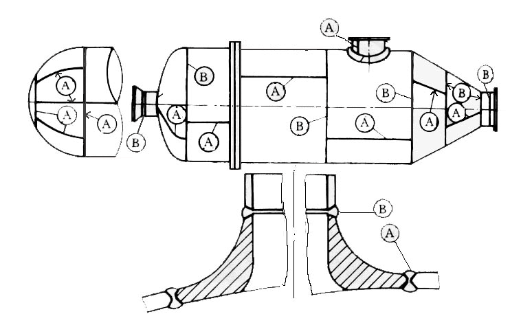
5. All welded joint of category A and B (see figure below) should be non-destructive examined (RT or UT) in accordance with the relevant standards and design drawing.
Scheme of Category A and Category B Welded Joints
The joint efficiency shall be determined according to the type of welded joint of the welded pressure parts and the percentage of NDE. Table 2 gives the stipulations for the joint efficiency.
|
Table 2: Joint Efficiency of Welded Pressure Vessel |
||||||||||
|
|
Full NDE |
Spot NDE |
||||||||
|
Steel |
Nonferrous metal |
Steel |
Nonferrous metal |
|||||||
|
Al |
Cu |
Ni |
Ti |
Al |
Cu |
Ni |
Ti |
|||
|
Butt joint as attained by double welding or by other means having the same quality as full penetrating double welding |
1.0 |
0.85 |
0.85 |
0.85 |
0.90 |
0.85 |
0.80 |
0.80 |
0.80 |
0.85 |
|
Single-welded butt joint with backing strip |
0.90 |
0.80 |
0.80 |
0.80 |
0.85 |
0.80 |
0.70 |
0.70 |
0.70 |
0.80 |
|
Single-welded butt joint without backing strip |
/ |
/ |
/ |
/ |
/ |
/ |
/ |
0.65 |
0.65 |
/ |
|
Note: a. NDE in the Table means RT or UT for steel pressure vessels and RT for non-ferrous metal pressure vessels in principle. Full NDE means 100% RT or UT; and spot NDE means 20% or 50% (for ferrite steel low temperature pressure vessel) RT or UT. b. The upper limit of joint efficiencies for nonferrous metal pressure vessel is for welded joint fabricated by metal inert-gas welding, The lower limit is for welded joint fabricated by gas tungsten arc welding. c. The words “by other means having the same quality as full penetrating double welding “ in the Table means the welded joint welding by one side which can assure good weld appearance at both side. In this case, it should be qualified with the same measures as for welding by both sides (including the qualification of welding testing plate). The welds by using argon shielded arc welding in backing welding or using ceramic or copper backing pads are the examples. |
||||||||||
b. The upper limit of joint efficiencies for nonferrous metal pressure vessel is for welded joint fabricated by metal inert-gas welding, The lower limit is for welded joint fabricated by gas tungsten arc welding.
6. The design pressure of liquefied petroleum gas (LPG) vessels operated at ambient temperature should base on the actual saturated vapor pressure of the mixed compositions of LPG at a temperature not lower than 50 °C. The limitation of LPG compositions and the corresponding working pressure shall be noted on the design drawing.
7. Neither lap joint nor cruciform joint is permissible for connecting shell to shell, shell to head and for connecting welds in welded heads.
8. One hand hole or two hand holes (for those vessels impossible to fit man-hole) should be provided for the pressure vessels with inner diameter not less than 500mm (except for those vessels, such as, jacket vessel, heat exchangers where the opening on the vessel are not allowed).
9. The safety interlocking devices shall be provided for pressure vessels with quick-actuating doors (closures).
Article 55
Requirements for pressure vessel steels
1. The materials for pressure components of pressure vessel shall be used within the applicable range of relevant standards.
2. The phosphor and sulfur contents of the carbon steel and low-alloy steel used for main pressure components of welded pressure vessel shall not be greater than 0.030% and 0.020% respectively.
3. The carbon contents in carbon steel and low-alloy steel used for main pressure components of welded pressure vessel shall not be greater than 0.25%, and the carbon equivalent Ceq should not be more than 0.45%. If the carbon and low-alloy steel, which carbon contents are greater than 0.25%, are necessarily needed, the manufacturer shall meet all the following requirements:
1). Obtaining agreement and acknowledge of the customer in advance,
2). Carbon equivalent Ceq of the material should not be greater than 0.45%,
3). Weldablity test report and welding procedure qualification report of the material should be provided, and report safety supervision administration of AQSIQ for review and approval.
4. For those quenched and tempered low-alloy pressure vessel steel, if the specified
minimum tensile strength in the relevant standard is equal to or greater than 540MPa, the phosphor and sulfur contents shall not be greater than 0.020% and 0.015% respectively. The welding cracking sensitivity coefficient Pcm shall not be greater than 0.25%, and the weldablity test report and welding procedure qualification report of the material shall be provided to safety supervision administration of AQSIQ for review and approval.
Note:
a. Ceq=C+Si/24+Mn/6+Ni/40+Cr/5+Mo/4+V/14
b. Pcm=C+Si/30+(Mn+Cu+Cr)/20+Ni/60+Mo/15+V/10+5B
5. Impact toughness of the low alloy steel plate for the proper of transportable pressure vessel shall be conducted. The sampling quantity of the impact test is two steel plate per batch and the test temperature should be -20 °C or per instruction on the drawing. The requirements and acceptable value of the impact test should conform to the applicable provisions in Table 3.
|
Table 3: Requirements for Impact Test and Acceptable Impact Toughness Value |
|
|
Minimum standard tensile σb ( MPa) |
Average impact energy value of three test |
|
Specimen size: 10 x 10 55 mm |
|
|
≤ 450 |
18 |
|
> 450 ≤ 515 |
20 |
|
> 515 ≤ 650 |
27 |
|
Note: |
|
6. The rimmed steels are not permitted in manufacturing the pressure components of pressure vessel.
7. The use of cast irons for pressure components in pressure vessel should accord to the requirements as specified in Table 4. Furthermore, they must not be used for pressure components in the following pressure vessels:
1) The pressure components of pressure vessels used to contain lethal, high-poisonous or middle-poisonous substances.
2) The pressure vessel for containing flammable media with design pressure equal to or more than 0.15 MPa.
3) Waste heat boilers with shell and tube type.
4) Transportable pressure vessels.
|
Table 4 |
||
|
Type of cast iron |
Design Pressure [MPa] |
Design Temperature [ °C] |
|
Grey cast iron |
0.8 |
0 to 250 |
|
Nodular or malleable cast iron |
1.6 |
-10 to 350 |
Article 56
Requirements for manufacture
1. Cold-formed carbon steel and low-alloy steel convex heads should conduct stress-relieving heat treatment after cold forming.
2. The following pressure vessels should conduct block post-welding heat treatment for relieving residual stress:
1). The pressure vessels used to contain lethal, high-poisonous or middle-poisonous substances.
2). The pressure vessel with wall thickness more than 16 mm and design temperature lower than -20 °C.
3). The carbon steel pressure vessel with wall thickness more than 32 mm (or more than 38 mm, if the welding preheat temperature is more than 100 °C).
4). The low alloy steel pressure vessel with wall thickness more than 30mm (or more than 34mm, if the welding preheat temperature is more than 100 °C).
5). All Cr-Mo alloy steel pressure vessels.
3. For pressure vessels used for storage of mixed LPG at ambient temperature or for other working media which may induce stress corrosion, each steel plate should be examined by UT and the post welding heat treatment should be made for stress relieving.
4. For those pressure vessels, which is designed by fatigue analysis, the reinforcement of welds in category A, and category B butt-joints shall be removed; all welded joints shall have smooth transition.
5) All corrugate plate-and-shell type heat exchanger shall have dismountable and cleanable structure.
Article 57
Requirements for inspection
1. Each of the following pressure vessels should produce a longitudinal product welding test plate:
1) The pressure vessels made of Cr-Mo alloy steel or material with minimum specified tensile strength more than 540 MPa in the relevant standard.
2) The pressure vessels with design temperature of less than -20 °C and requiring low temperature impact test.
3) The pressure vessels requiring heat treatment to assure the mechanical properties of its steel plate.
4) The pressure vessels used to contain lethal or high-poisonous substances,
5) The pressure vessels with design pressure more than 10 MPa,
6) The non-ferrous metal pressure vessels with design pressure more than 1.6 MPa,
7) The welded pressure vessels made by dissimilar metals,
8) Spherical tanks,
9) Transportable pressure vessels.
2. NDE on welded joints of pressure vessel should accord to the requirements as specified in the drawing. The Category A and category B welded joint of the following pressure vessels shall perform 100% RT or UT but the RT should be adopted if the wall thickness of the vessel is equal to or less than 38 mm.
1) The class III pressure vessel.
2) The reactors and storage pressure vessels among class II used to contain lethal, high-poisonous or middle-poisonous substances.
3) The pressure vessels with design pressure more than 5.0 MPa.
4) The tube and shell waste heat boilers with design pressure more than 0.6 MPa.
5) The pressure vessels with joint efficiency of 1.0 (except for the pressure vessels which use seamless tube as shell and the close circumferential weld, but the later should use the suitable welding method and parameter to assure the welding quality).
6) The pressure vessels that can not perform inner examination or pressure-test after put in use.
7) The carbon steel pressure vessels with wall thickness more than 30mm and low alloy steel or stainless steel pressure vessels with wall thickness more than 25 mm.
8) The pressure vessels made by Cr-Mo low alloy steel or steels with specified minimum tensile strength more than 540 MPa in the relevant standard.
9) The vessels used to contain lethal or high-poisonous substances.
10) The pressure vessels using pneumatic pressure test other than hydrostatic-test.
11) The pressure vessel designed and constructed per stress analysis standard.
12) Butt joints in inner cylinder of multi-layered pressure vessel and in each cylinder of hot-shrink-fitted pressure vessels.
13) The pressure vessels which should be examined with 100% RT or UT in accordance with design drawing.
3.Except for the requirements as specified in 2. Of this Article, it is permissible to apply spot NDE for category A and B welded joints. The percentage for spot NDE shall not be less than 20% of the length of each weld and not less than 250 mm. But all of the following welded joint should be non-destructive examined and the acceptable criterion should be in accordance with the requirements of the pressure vessel.
1). All of the T-joints.
2). All welded joints within opening area (the area within the circle with diameter of 1.5 times of the opening diameter and having the same center of the circle as the opening).
3). The welded joint to be covered by reinforcement rings, saddles or pads.
4). Butt joint in welded head or welded tube plate.
5). All butt joints in nozzles with a nominal diameter greater than 250 mm. The percentage and acceptable criteria shall be same as that of the welded joint in the vessel proper.
4. It is not allowed to exempt NDE of the welded joint by decreasing its joint efficiency.
5. The test pressure, test medium, temperature of test medium, pressure holding time and test results shall be included in the pressure test and leak test report. The pressure test and leak test report shall be provided to the customer together with the vessel.
Article 58
Basic requirements for gas cylinders
1. All gas cylinders must be designed and manufactured in accordance with the Chinese national standards. In addition, the design documents of them shall be appraised before type testing. In the case of lack of Chinese standards, the manufacturer should report the applied standard and related technical document to the safety supervision administration of AQSIQ for review and approval. Among them, the key items related to the safety quality of gas cylinder, such as, design temperature, design pressure, bursting testing, NDE, mechanical properties, must not lower than the requirements as specified in the corresponding Chinese national standard.
2. The color marking of the imported cylinders shall be in accordance with the provisions in Chinese mandatory national standard GB 7144.
![]()